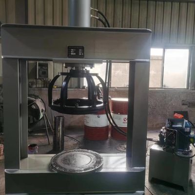
The TP120 - E solid tire mounting machine is meticulously crafted from steel plates. With a rated pressure of 120 tons, it is specifically designed for the dismounting and mounting of solid tires with rims ranging from 8 inches to 15 inches (compatible with tire specifications 825 - 15/300 - 15). It is widely used in the maintenance scenarios of solid tires for forklifts, engineering machinery, etc., enabling efficient and precise tire handling operations.

| Parameter Category |
Technical Index |
Description |
| Model |
TP120 - E |
Made of steel plates |
| Capacity |
120 Tons |
Meets the needs of heavy - duty tire handling |
| Max. Tyre |
825 - 15/300 - 15 (inches) |
Compatible with mainstream solid tire specifications |
| Total Length |
1300mm |
Compact layout, space - saving |
| Total Width |
600mm |
|
| Total Height |
2050mm |
|
| Plate diameter (inside - outside) |
530 - 640mm |
Adjustable for different rim sizes |
| Work platform ret height |
350mm |
Facilitates tire and rim placement |
| Working space |
1000*850mm |
Provides sufficient operating space |
| Operating Pressure |
15Mpa |
Stable hydraulic output, ensuring handling effect |
| Cylinder Max.stroke |
500mm |
Meets the stroke requirements for tire handling |
| Oil Tank Capacity |
90 Liters |
Ensures continuous and stable operation of the hydraulic system |
| Electro - Motor |
4.0kw (380v) |
Powerful, suitable for industrial power standards |
| Weight |
1000kgs |
Stable structure, easy for site arrangement |
| Press Speed/time |
2min |
Efficient operation, reducing maintenance time |
The fuselage is welded from high - quality steel plates and undergoes strict stress treatment. It has excellent deformation and impact resistance, can withstand long - term high - frequency heavy - duty operations, ensures stable equipment operation, and is suitable for complex maintenance environments.
The hydraulic system has a stable pressure of 15Mpa, and the hydraulic cylinder stroke is precisely controllable (maximum 500mm). Combined with a high - precision pressure plate, it can ensure uniform fitting and precise handling of tires and rims, avoiding damage to tires or rims due to uneven pressure.
Equipped with exclusive tooling such as TOOL - I (press barrel), TOOL - II (guide ring), TOOL - III (backing ring), and TOOL - IV (guiding rod), covering 8 - inch to 15 - inch rims. The tooling can be easily replaced, enabling quick handling of different specifications of tires, and improving operation efficiency and compatibility.
According to the tire rim specifications (8 inches - 15 inches), select the corresponding TOOL series tooling (such as TOOL - I to TOOL - IV for 8 - inch rims). Check for wear and deformation on the tooling surface to ensure precise alignment of the tooling with the equipment.
- Place the rim stably on the workbench, and use tooling (such as guide rings and guide rods) for auxiliary positioning to ensure the center of the rim is aligned with the center of the pressure plate.
- Fit the solid tire onto the rim and adjust it to a preliminary fitting state.
- Start the equipment, the hydraulic system drives the pressure plate to press down slowly, and apply pressure at a constant speed (observe that the pressure value is within the working pressure range) until the tire is completely pressed into the rim to complete the mounting.
- Use tooling such as backing rings to fix the rim, and align the press barrel with the separation part of the tire and rim.
- Start the equipment, the pressure plate applies pressure, and cooperate with tools such as crowbars for assistance to gradually separate the tire bead from the rim to complete the dismounting. Pay attention to applying pressure at a constant speed during operation to avoid damaging components due to violent disassembly.
During operation, operators must wear safety shoes, protective gloves. Long hair should be tied up and a safety helmet should be worn. It is strictly forbidden to wear loose clothing and accessories to prevent being caught in the equipment or crushed. When the equipment is running, keep body parts away from the moving areas of the pressure plate and tooling, and maintain a safety distance of at least 1 meter.
Before starting, check the hydraulic oil level (should reach a reasonable scale of the oil tank volume). If the ambient temperature is lower than 10℃, run it empty for 3 - 5 minutes to preheat the hydraulic system first. Check whether the connecting bolts (especially the hydraulic cylinder and tooling fixing bolts) are loose and whether there is oil leakage in the hydraulic pipeline to ensure the equipment is in good condition.
If there is abnormal noise, excessive pressure fluctuation or oil leakage during the operation of the equipment, immediately press the emergency stop button, cut off the power supply. After the system pressure is completely released, contact professional maintenance personnel for repair. It is strictly forbidden for non - professional personnel to disassemble hydraulic and electrical components without permission to avoid safety accidents or equipment damage.
After daily operation, clean the oil stains and metal debris on the equipment surface to prevent debris from entering the hydraulic system or affecting the tooling accuracy. Check the wear of the tooling. If there is slight wear, repair it in time; if there is severe wear, replace the corresponding tooling to ensure handling accuracy.
- Weekly: Detect the cleanliness of the hydraulic oil. If the oil is turbid and the viscosity decreases, replace it with suitable anti - wear hydraulic oil in time (refer to the recommended model in the equipment manual).
- Every 3 months: Disassemble the hydraulic cylinder, check the wear of the piston rod surface coating and the aging of the seals. If necessary, replace the seals and repair the coating to ensure the sealing and smooth operation of the hydraulic system.
- Annually: Conduct non - destructive flaw detection on the welded structure of the equipment to identify potential structural hazards and ensure long - term safe and stable operation of the equipment.
Suitable for quick replacement of solid tires (such as specifications 825 - 15/300 - 15) of 3 - 10 - ton forklifts. In logistics parks, warehouses and other sites, it helps maintenance personnel to efficiently complete tire handling, reducing equipment downtime and ensuring the continuity of logistics operations.
Can be used for the maintenance of solid tires of small engineering machinery (such as small loaders, road rollers, etc.). With a pressure of 120 tons and precise tooling, it meets the handling needs of heavy - duty tires of engineering vehicles, suitable for the operation scenarios of after - sales service outlets and repair factories of engineering machinery.
As professional tire maintenance equipment, it covers the handling of solid tires of 8 - inch to 15 - inch. With complete tooling, it is compatible with the service of solid tires of different brands (such as Michelin, Bridgestone, etc.), improving the maintenance capacity and business scope of the outlets.
If customers have special tire specifications, power adaptation (such as non - 380V voltage) and other needs, they can contact the manufacturer for customized development, including tooling customization, electrical system adjustment, etc., to meet personalized operation scenarios.
The "TP120 - E Operation and Maintenance Manual" is attached with the equipment purchase. The manufacturer can provide online/offline operation training, covering safety specifications, equipment operation, daily maintenance, etc. The equipment has a 12 - month warranty period (excluding wearing parts). During the warranty period, faulty parts are repaired free of charge. Technical consultation and spare parts supply services are provided for life to ensure the continuous and stable operation of the equipment.
Note: The equipment undergoes strict pressure testing and function verification before leaving the factory to ensure performance compliance. During actual operation, it is necessary to strictly follow the operation specifications and maintenance requirements to ensure the service life of the equipment and operation safety. For detailed equipment drawings, tooling adaptation plans or on - site demonstrations, you can contact the manufacturer for exclusive support

 Your message must be between 20-3,000 characters!